Yokogawa EJA110E User Manual Page 83
- Page / 85
- Table of contents
- TROUBLESHOOTING
- BOOKMARKS
- IM 01C25B01-01E 1
- Contents 2
- Revision Information 4
- 1. Introduction 5
- <1. Introduction> 6
- 1.2 Warranty 7
- 1.3 ATEX Documentation 8
- 2. Handling Cautions 9
- IMPORTANT 12
- 2.9.2 CSA Certication 14
- 2.9.3 ATEX Certication 16
- 2.9.4 IECEx Certication 19
- 2.11 Pressure Equipment 21
- Directive (PED) 21
- 2.12 Low Voltage Directive 21
- 3. Component Names 22
- 4. Installation 23
- 4.3 Changing the Process 24
- Connection 24
- 4.4 Swapping the High/Low 25
- <4. Installation> 26
- High Pressure Type) 26
- 5. Installing Impulse Piping 27
- (Figure 5.2) 28
- (Figure 5.3) 28
- Examples 30
- 6. Wiring 31
- 6.4 Wiring 32
- 6.5 Grounding 33
- Load Resistance 33
- 7. Operation 34
- 7.2 Zero Point Adjustment 35
- 7.3 Starting Operation 36
- 7.5.1 Draining Condensate 37
- Range-setting Switch 38
- 8. Maintenance 40
- 8.4 Disassembly and 42
- Reassembly 42
- Assembly 43
- 8.5 Troubleshooting 45
- <8. Maintenance> 46
- 9. General Specications 49
- Normal Operating Condition 51
- Physical Specications 53
- 9.2 Model and Sufx Codes 54
- Model EJX120A 55
- Model EJX130A 56
- Model EJX310A 57
- Model EJX430A 58
- Model EJX440A 59
- Model EJA110E 60
- Model EJA120E 61
- Model EJA130E 62
- Model EJA310E 63
- Model EJA430E 64
- Model EJA440E 65
- 9.3 Optional Specications 67
- Model EJ110 70
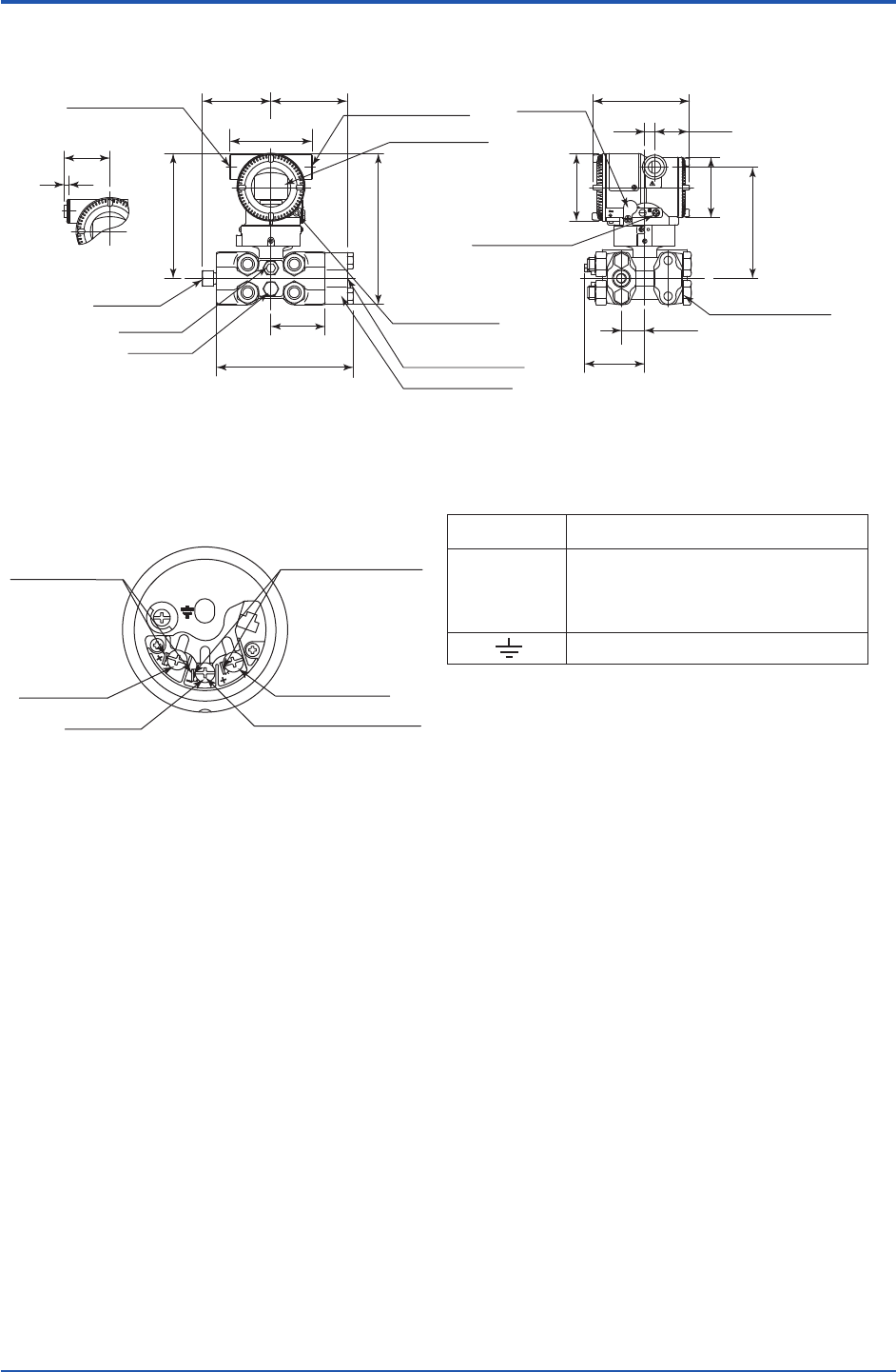
- Unit: mm (approx. inch) 71
- F0906.ai 72
- F0907.ai 72
- F0908.ai 73
- F0909.ai 74
- Model EJ130 75
- F0911.ai 76
- F0912.ai 77
- F0913.ai 78
- F0914.ai 78
- Model EJ430 79
- F0916.ai 80
- F0917.ai 81
- F0918.ai 81
- Model EJ440 82
- F0920.ai 83
Related products and manuals for Sensors Yokogawa EJA110E
 (4 pages)
(76 pages)
(85 pages)
(64 pages)
(41 pages)
(78 pages)
(7 pages)
(6 pages)
(40 pages)
(85 pages)
(10 pages)
(96 pages)
(76 pages)
(72 pages)
(67 pages)
(52 pages)
(85 pages)
(55 pages)
(83 pages)
(9 pages)
(4 pages)
(76 pages)
(85 pages)
(64 pages)
(41 pages)
(78 pages)
(7 pages)
(6 pages)
(40 pages)
(85 pages)
(10 pages)
(96 pages)
(76 pages)
(72 pages)
(67 pages)
(52 pages)
(85 pages)
(55 pages)
(83 pages)
(9 pages)
© 2020, manymanuals.com. All rights reserved. | 0.050 s |
 Manymanuals.com
 Manymanuals.de
 Manymanuals.fr
 Manymanuals.it
 Manymanuals.pl
 Manymanuals.cz
 Manymanuals.es
 Manymanuals-pt.com
Comments to this Manuals